Description | Download
Description |
MIDI Merge Box 2×1 is tool what merges MIDI data from two inputs to one output. The known fact is that it is impossible to merge the data directly as a logical sum of the MIDI data. That solution generates nonsensical data. So it is necessary to use special algorithm for the data merging. This can guarantee only processing by a microcomputer.
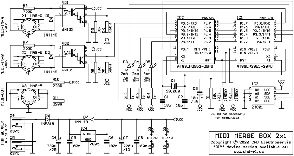
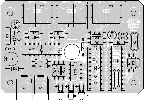
Pictures below show schematics diagram and PCB appearance. The circuit is as simple as possible. All activities control microcomputers (IC1, IC2). Device functions are controlled by parameters stored in non-volatile memory (IC3). Actual status of device operation indicate three LEDs (D3, D4, D5). Both MIDI inputs are isolated by optocouplers (VD1, VD2). The IC4 voltage stabilizer enables the device to be connected to power supply voltage with large range (from 8 to 20 volts DC). D4 diode protects the device against reverse polarity of the supply voltage. Current consumption of the device is about 30 mA.
Complete manufacturing documentation (records for PCB manufacturing, software for IC1 and IC2, images, etc.) and manual how to use the merge box are available in Dowload section.


Schematics diagram:
PCB:
Download |
| Documentation, Manual | PDF document |
| Source Files Archive | ZIP archive with records for PCB manufacturing and program codes |
