Description | DIN-SYNC Bus Signals | Hardware Interconnection
Description |
The DIN-Sync bus enables time synchronization of analogue devices. DIN-Sync bus can be found on many older sequencers, drum-machines, basses, microcomposers etc. All of these devices can be to start and stop together from a single control transmitter. Simultaneously, it is ensured that correct playback speed of all connected devices will be adjusted automatically if any change of tempo occurs on control transmitter.
DIN-Sync Bus Signals |
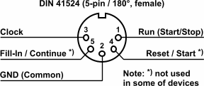
Complete DIN-Sync bus uses four signals and one common ground:
CLOCK
This signal determines the global tempo. With its help, tempo generators of all connected devices are synchronized. A control transmitter should generate clock pulses continuously, including when the RUN signal is not active (a song is not playing). However, some devices do not comply that. 24 clock pulses are transmitted during one quarter note duration (24 PPQN – Pulses Per Quarter Note). But there are some exceptions (e.g. Korg KPR77 – 48 PPQN, Roland CR68 and CR78 – 12 PPQN).RUN (START/STOP)
This signal starts and stops a song playback. The playback is enabled (RUN or START status) if the signal is active (level “1”). Immediately after the signal deactivation (level “0”), the playback is stopped (STOP status). Turning on (activation) of the signal is usually done by pressing “Start” or “Start / Stop” control button on the data transmitter. Turning off (deactivation) of the signal is then done by pressing “Stop” button or repeated pressing of the “Start / Stop” button.RESET / START
Reset pulse sets the playback position to start of the song . The Reset pulse is usually generated simultaneously with the RUN signal activation when the “Start” or “Start / Stop” button on the data transmitter is pressed.FILL-IN / CONTINUE
FILL-IN pulse is generated by a data transmitter when “Continue” button is pressed. In case a song is not playing, the RUN signal is activated simultaneously and playback of a song is started. Usage of the signal is different in a receivers. Some receiving devices only continue playing the song from where it was previously stopped, other devices insert a break sequence into playing song, etc.
DIN-Sync bus signals:
All signals are working with 5-volt positive logic (TTL). This means that idle state signal (logic zero) is represented by potential from 0 to 0,8 volts and the active signal (logic one) is then represented by potential from 3,6 to 5 volts. The RUN signal is continuous – playback takes place throughout the signal activity. The CLOCK, RESET and FILL-IN signals are impulses only. The length (duration) of these pulses is 1 milliseconds and more.
Not each device equipped with DIN-Sync bus can handle all of its signals. All devices must be able to transmit or to receive respectively the CLOCK and the RUN signals – a song playback can’t be synchronized without these two signals. However, implementation of the RESET and the FILL-IN signals in a DIN-Sync devices is not frequent. The device transmitting or receiving respectively these signals can be encountered only rarely.
Hardware Interconnection |
DIN-Sync bus uses DIN 41524 connectors (female, 5-pin / 180°). The bus is unidirectional. Two separate connectors are used for input and output. Sometimes, only one connector is used for both input and output and function (input / output) of this connector is selectable by a switch (eg. Roland TR-808). However, not all devices can transmit and also receive DIN-Sync signals. In that case, the device is equipped only with a single input or output connector with fixed functions.
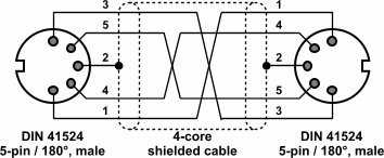
Wiring of DIN-Sync connectors:
DIN-Sync output and DIN-Sync input of the follow-up device are interconnected “pin-to-pin” way. For DIN-Sync connection, standard shielded cable for connecting audio devices can be used. Cable quality (impedance, capacitance) has only little influence to distortion of transferred data. It does not apply practically when the cable length is approx units of meters.
Standard DIN-Sync cable:
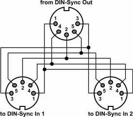
Sometimes, it is necessary to transmit the signals from one DIN-Sync output to multiple receivers. If the transmitter has only one output of DIN-Sync data, it is possible to use a specially made “Y” cable for branching the signals. And again, “pin-to-pin” way of wiring of all connectors is used. Output circuits of DIN-Sync bus are usually very powerful so this kind of branching of signals from one output can also be implemented for more inputs than just two.
DIN-Sync “Y” cable:
